PTS Logo


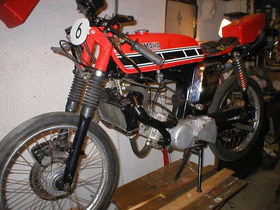
The YAMAHA FS1E Twin exhaust port water cooled project


This was made around the time that it was realised that hydrocarbons couldn't be removed from two-stroke emmissions.

Basis of this is was a bad time to be inventing new types of two stroke engines and my invention was doomed from the start.

Yamaha FS1E DX LC


Two strokes above 125cc were no longer sold in the UK and were banned in the USA. Mostly just racing bikes, mopeds and chainsaws were the only ones allowed.

In four stroke engines hydrocarbons are dealt with by catalytic converters but these could not be used on two strokes as there were always some partially unburnt gasses.


As it was well known that enlarging the exhaust port of a two stroke engine increased power, it was also well known that increasing the port width to about 70-73% of the

chordal width of the bore was the approximate maximum width limit or the piston rings would abrade and snag in the exhaust port giving them a very short life.

This led to the design of a bridged exhaust port such as was used in the RM125 Suzuki which enabled a wider area and more power.

I had this crazy idea to use two opposite exhaust ports of around 60% chordal width making a collosal 120% total chordal width when I was about 19 years old

and I built this home made water cooled Yamaha FS1E engine modification around 1988.

I also went to the trouble of applying for a UK patent application to give me partial protection.


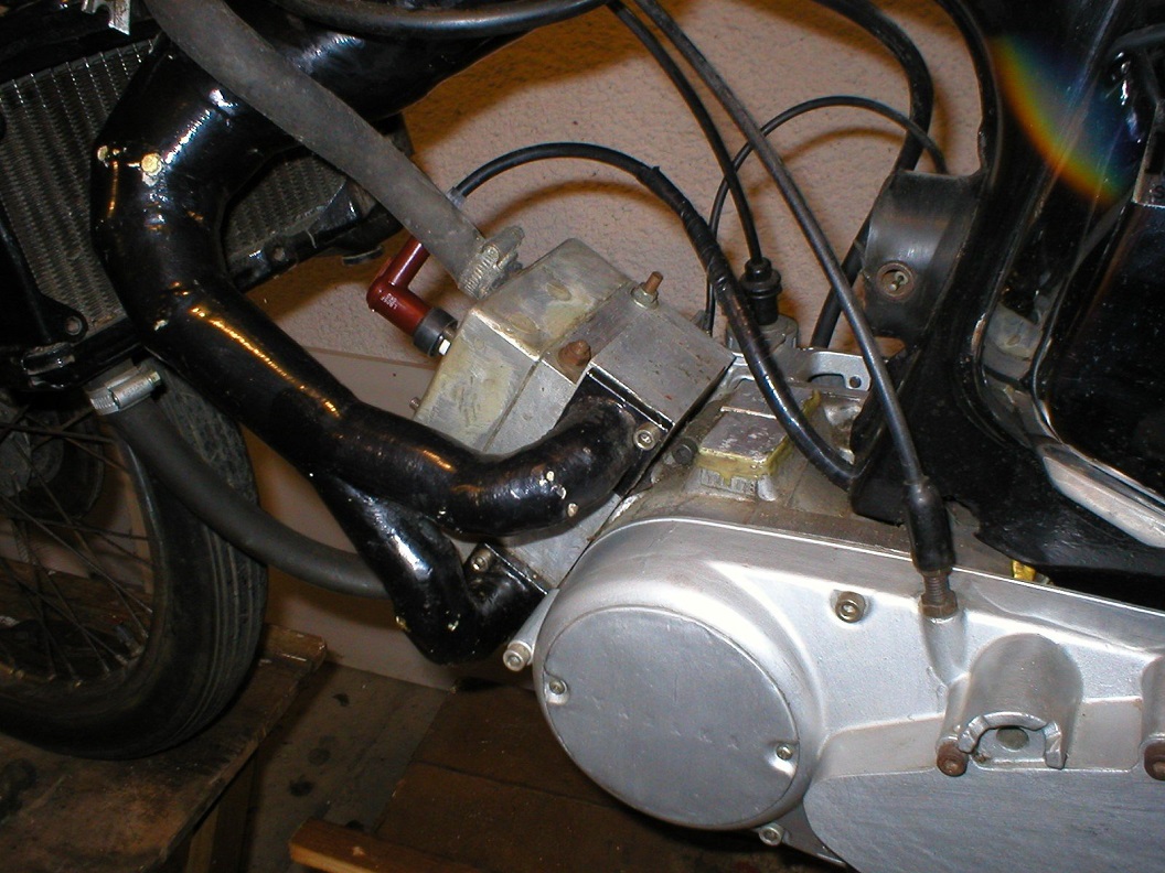
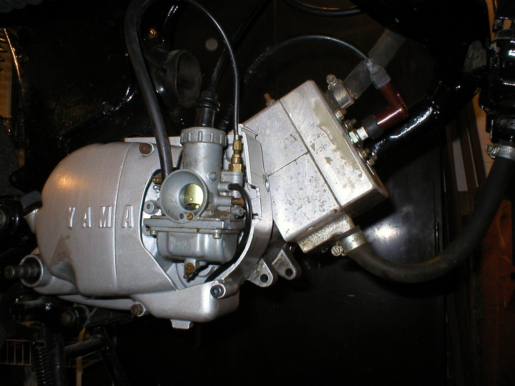
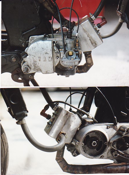
There were two designs of barrels, both were identical from the view point of the piston on the inside of the cast iron liner but one version ( pictured ) fed the two

opposite ports into a single expansion chamber.

The other more powerful version had two separate expansion chambers and it went a lot faster, likely because the ports were straighter and there was less confusion in the gas flows.

The first images are of the two into one expansion chamber design. I expect it was a bit slower because the pressure pulse wave became confused on leaving the

ports instead of having a smooth journey up and down two tubes.

The main point I got from this experimental design was analogous to a kitchen sink with two plug holes about 4 inches apart.

There would be a dead spot in the space between them which would impede a smooth flow out to the drain.

Inside the engine the pressure pulse would have been split in two directions at once with some kind of strange vacuum effect in between the ports.

(This would be different to the desired vacuum effect of the negative sign wave pulse caused by the expansion chamber itself )

Reflecting on this more recently it might have actually impeded the gas flow out of the exhausts.


The negative sine pulse returning to suck up the fuel-air mix through the transfer port would be fine though.

After a lot of testing I observed that it could not make more power than a regular single port design but it was not slow.

The spark plugs were always hyper clean and it awlays started easily with the first spin of the back wheel in 2nd gear by hand, easier than a normal Fizzy would start.

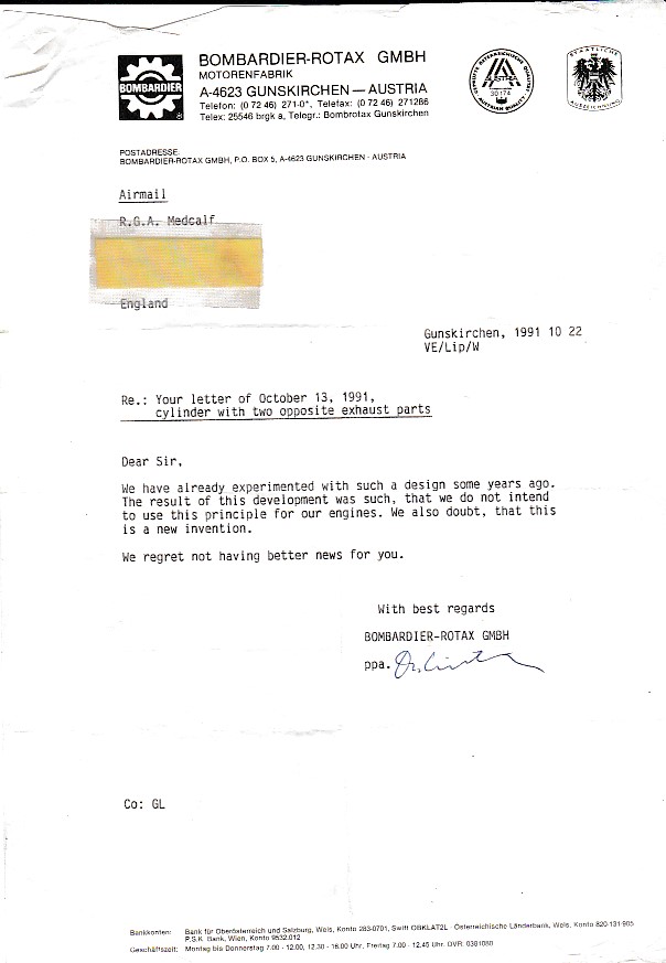
Unknown to me at the time the opposite exhaust port design was not new as Rotax told me in their letter that they already tried it "some years ago".

(See letters below)

Yamaha FS1E DX LC


The water cooling was a great success and used a thermosyphonic action with no pump. It always kept nice and cool the good thing about the thermosyphon method

is that the hotter it gets the fast it flows around and vice versa.

The image below shows clearly the top rubber pipe let the hot water rise up and this entered into the top of the radiator which cooled and fell and this ran down into

the bottom pipe thus making a cooling loop. The radiator I used was off some random engine from a breakers yard.

If you use this approach and find the engine runs too cool, it is a simple matter to blank off some of the surface area of the radiator with a thin sheet of steel to

reduce air flow through it just like the London taxis used to do.


Yamaha FS1E DX LC


The bigger carb was never set up quite right although the main jet size at full throttle was correct someone with good carburettor knowledge could get this running

 faster, probably in hindsight it did not need to be so big as the extra size would only help if the engine was screaming its nuts off, overall performance probably

 would have been fine with something that was around 18mm bore assuming it could be made to fit.

 There was a wider spigot brazed onto the disc valve cover and a wider o ring seal also.

I have three different sets of expansion chambers I made for this.

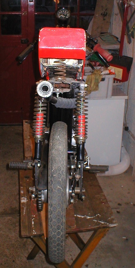
With a home made sprung loaded steel bucket seat and a Yamaha RD 200 Speedo fitted it could just about pass as presentable.


Yamaha FS1E DX LC


The photos below show the more powerful design of barrel with straight exhaust ports and dual expansion chambers and truly free flowing pressue pulse waves.

With this version there was no strange pulsing sounds coming out of it, just some good music to its sound when coming on the pipe.

Yamaha FS1E DX LC


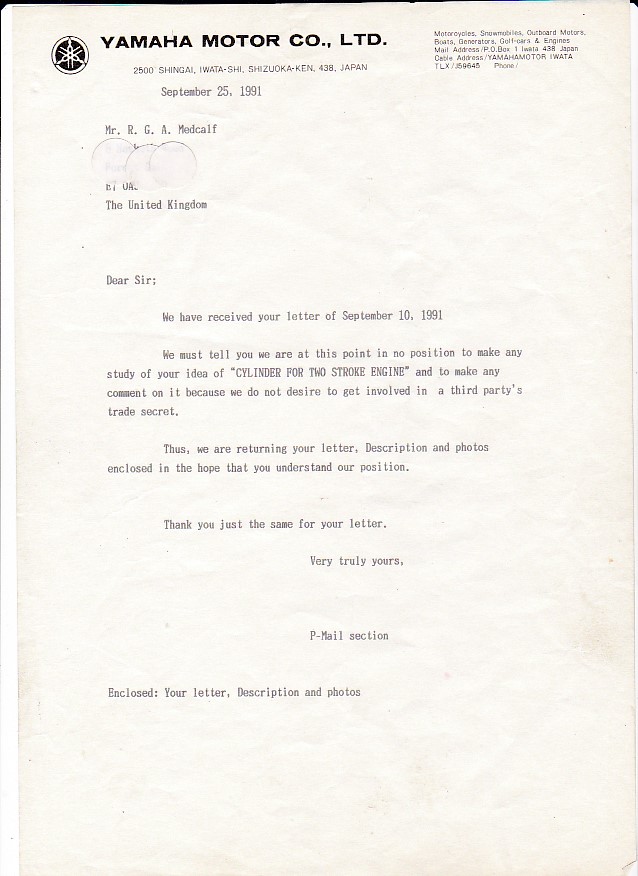
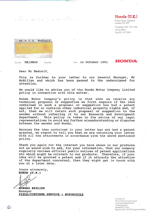
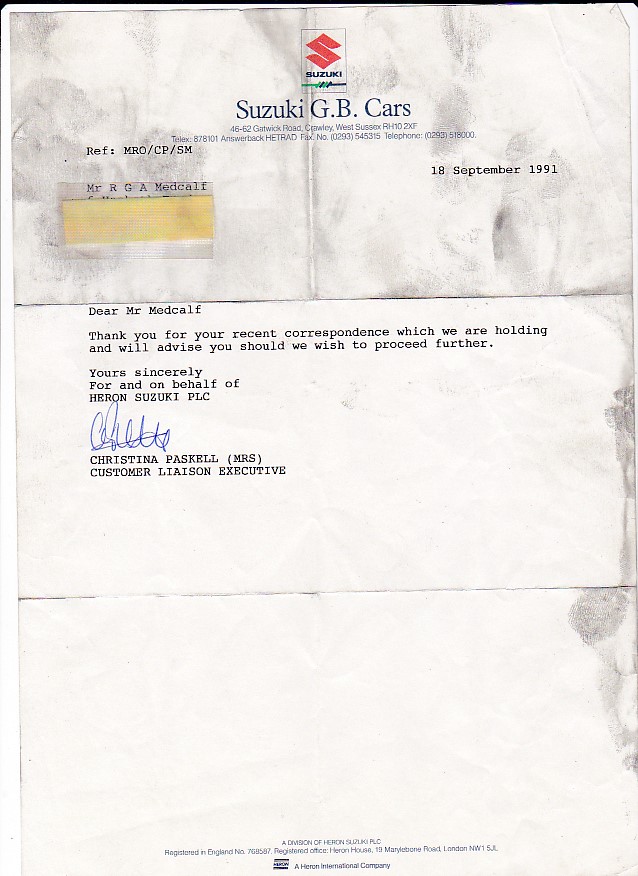
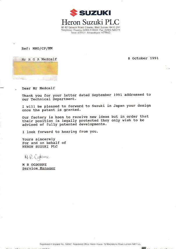
I sent the pat pending design off to manufacturers and Suzuki were quite interested, the others like Honda

said they would have to wait until the patent was granted. Rotax and Kawasaki flatly said not interested, the letter from Yamaha was strange.
 
-

The first letters from Suzuki was read with great excitement. Hence being covered in my greasy dabs.

Yamaha FS1E DX LC 

2nd letter from Heron Suzuki was very positive.

Yamaha FS1E DX LC


-

The letter from Yamaha was a bit mysterious and they sent everything back to me.

They did not mention any objection to me butchering one of their beloved Fizzys though.


Yamaha FS1E DX LC
 

Letter from Rotax stating they already tried this idea.

Rotax together with Morbidelli are widely regarded as being the Worlds best racing two stroke engine makers so I was at least

happy to know that great minds were thinking alike. These things just have to be tried out don't they?
 
Yamaha FS1E DX LC
 
A nice letter from Honda
 
Yamaha FS1E DX LC

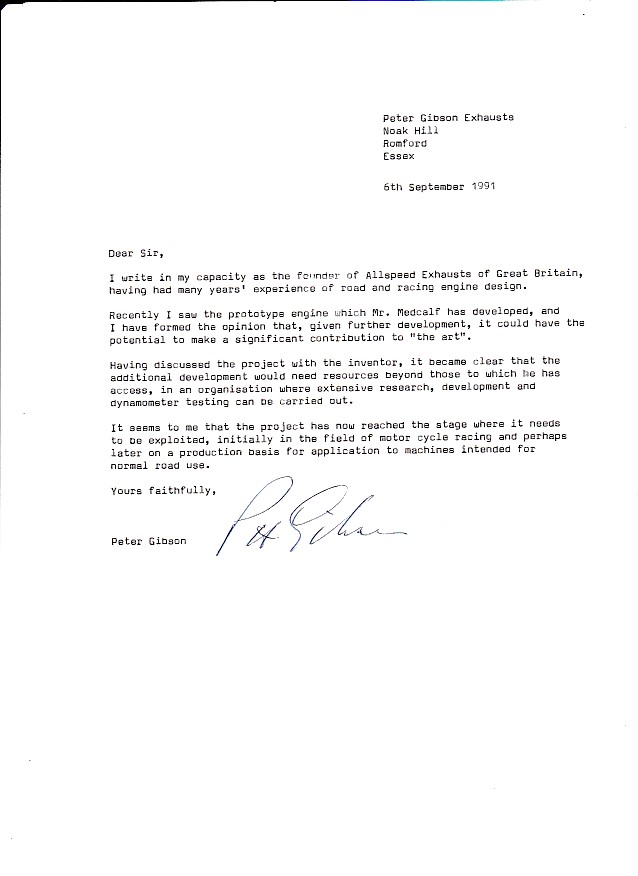
Letter from Peter Gibson of Allspeed exhausts

I learned a few things from Peter as he was one of the best exhaust makers in the UK and a very helpful man with a one man operation.

1. On expansion chamber design, if the tail pipe exit is connected at the end of the cone this is a high pressure area and thus will make more noise than is ideal.

If you push the stinger pipe down inside to a low pressure area ( where the end cone meets the straight section ) you have a much quieter sound.

If you ever heard the lovely tinny sound than a Yamaha IT 175 or a Honda CR 250 or even an RD 250LC kitted with Allspeeds then that is what you get if you

 push the stinger pipes deeper inside the last cone.  I also note that if this happens to make the stinger longer than is needed and thus more restrictive

 then its diameter must be widened to prevent over heating due to a rise in back pressure.

2. When the noise level laws got changed the regular Micron and Allspeed pipes were above the limit so Peter had to work out how to reduce the noise, surprisingly

a large part of the noise was emitted from the exterior surface of the pipe itself instead of just the tail pipe. The solution is showed me was they used a double

skin in the sense of two layers of 1mm thick tubing. Also it surprised me to learn that the double skinned expansion chamber made less power than the single skin

version. I later learned from Ed Seykota on his radial momentum page that it can be observed with a strobe light that the chamber actually swells and shrinks

over the course of the suck, squeeze, bang blow cycle that engines make. So it seems certain that a rigid pipe which cannot expand and contract does not work as

well as one which is flexible. Rather an odd thing to realise that. Think how difficult it would be to make double skinned pipe with welds and curves.

I used the internal tailpipe logic in any other expansion chambers I made and got the nice tinny crackle sound and lower decibels.

Compare that to the sound of a Fizzy that sports a Micron exhaust and you will get the point.

Yamaha FS1E DX LC
 

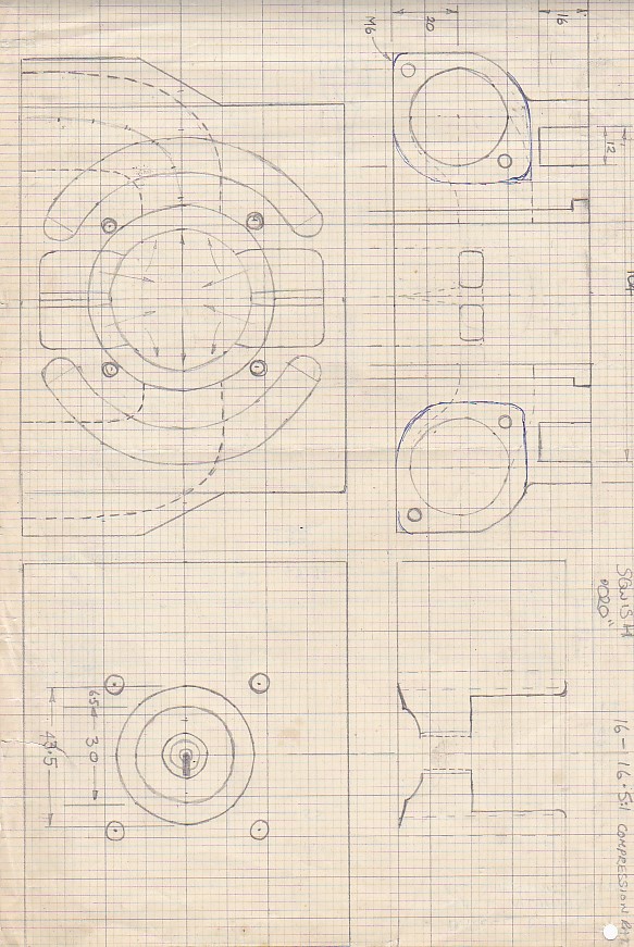
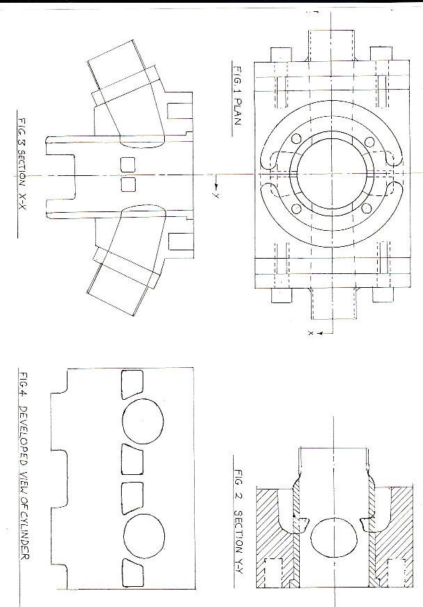
Design of the two into one expansion chamber cylinder ( less effective version ) Note the upon its first journey out of the cylinder the

exhaust gases start off by being made to do a sharp 90 degree turn which must impede flow to some degree.

The same head was used in both designs and both had a squish clearance of 20 thousands of an inch

 
Yamaha FS1E DX LC
 

Drawing of the more powerful and better design with dual straight opposite exhaust ports going into separate expansion chambers

 
Yamaha FS1E DX LC
 

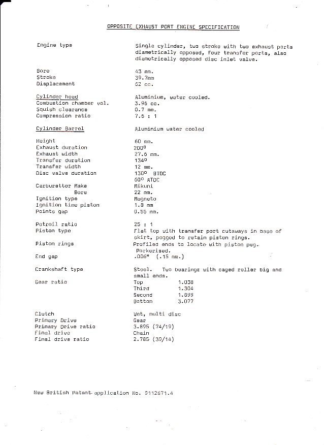
Water cooled FS1E Technical Specifications : Only a single top piston ring was used and it was re dowled so the ring ends missed the ports.

 
Yamaha FS1E DX LC
The next part of this story is related to another design I came up with, but someone else went ahead with it and I did not...
 
Yamaha FS1E DX LC


The dual disc valve per cylinder invention was more succesful in terms of ideas and it was actually made into a race engine design by Exactweld

It made about 72 bhp but had a high speed misfired they could not work out. The rather clever design used the engine as part of the frame

thus saving a lot of weight and cost of materials, the engine of course has to be much stronger to stand the extra loads put on it.

You can read about it here in article featured in the Road Racer magazine from February - March 1987

Reading this gave me a shock to read as I had drawn the same design myself four years earlier in 1983.


Bio
The PTS Logo
Admin notes
Page expanded on December 19th  2023 after getting a lot of visits   -  New responsive page GA4 added canonical this. 5/5 html sm links added - replaces old page from 2006